Hacking the Atomi Smart Wifi Color String lights.

So lets get inside it to access the delicious center.

I decided to use a very high tech and surgical process to get inside this sealed waterproof case. Over the past year I have watched the videos of people trying to hack these and all of them do it the hard way. Nothing beats a welded plastic seam like a 2.5 pound sledge. So I sat down, calculated the weight, local gravity strength, average temperature in kelvin and the hardness of the bench and then grabbed the hammer and whacked it.
This worked better than I expected.... to be fair I already hacked one of these before writing this. This is my second set. The first time I tried to get info from a YouTube video and while entertaining, the video creator gave everyone zero information. his was also butchered pretty badly to get inside. You could use a dremel and carve off the side seams. That is what I did the first time..... The hammer worked better and was way more satisfying. It was not cold when I did this, room temperature was about 80F. and no I did not whack it hard. I started with some lighter love taps and hit it progressively harder until I saw a gap form.

Once the crack formed I tapped a few more times and then used a flat blade screwdriver CAREFULLY to pry it the rest of the way apart. Don't go shoving a screwdriver inside and whacking it around, there is a circuit board right there so take your time and be careful. The AC cord on mine got stuck to the bottom half, so I had to carefully pry it free from that and reattach it to the top half. (Top half has the button). if you go ripping on it like a caveman you will break something. The board is screwed to the top half with 3 screws as you can see in the next photos.
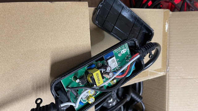
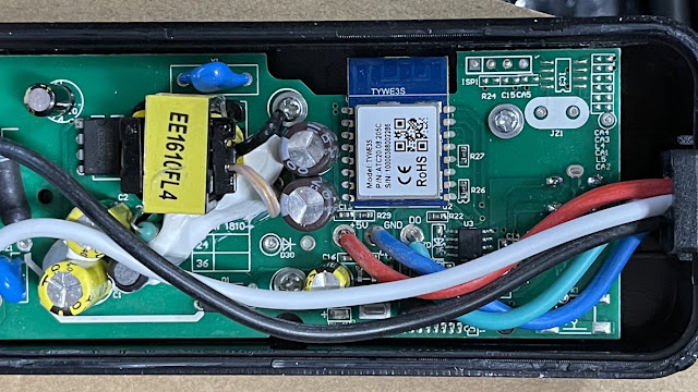
Insides showing the TYWE3S, the wires and pads we will use as well as the 8 pin chip we are going to rip off the board.

Once inside, we can start assessing what is going on here. AC voltage power supply to make 5Volts at about 2 amps and a separate 3.3v power supply for the ESP clone. the 4 pads at the top edge to the right of the ESP is the programming header. 3.3v/TX/RX/Gnd left to right. Between R27 and R26 is a pin 3rd from the bottom on the ESP on the RH side.... this is Gpio2 and what we will be using for communication. There is another chip under the wires at the bottom. This is a co-processor that does all that talking to the LED's. this thing is going to interfere with us. BUT U3, the 8 pin chip directly to the right of the green wire pad and above the white (yes the photo looks light blue) wire. is the chip used in all these LED's. if we remove that, the Co-Processor can not talk to the LED string and that is what we want. Removal of that little chip also removes a "phantom" LED from the string that does nothing. I think the engineers were using it as a buffer for the serial data, we will not need that.
During programming I ran into some issues. It kept acting like it was programming but failed. you will notice that the LED string lights up and does the dance mode when you plug in your programmer. so you have 2 choices. unsolder the 5V to the string,

For some reason, these product makers are hell bent on making garbage UI's instead of using something like WLED that destroys anything their best programmers could ever come up with..... and that is my target... run WLED on this. It's going to make this do a whole lot more, be controllable in a smart home AND be useful with SaCN DMX control.
A level shifter needs to change theESP 3.3V signal to the 5V signal the led string needs. there are tons of level shifters out there but one of the best is the 74HCT125. it does not need dual power supplies like most AND acts as a signal buffer. it's also more robust and overall a better option than anything else I have seen or used. Biggest advantage is it only needs a single popwer supply, your target voltage and a couple of ground connections ans signal in/out. This chip is available in SMD and DIP. I am using the DIP for easier soldering and I have about 20 of them.


Interesting thing about these strange LED driver chips they are TM1814 and if they do not get addressed and a constant data stream, they go into a color blink mode. This freaked me out for a while trying to figure out what the heck was sending them data so I started cutting wires and they kept blinking. Once I had the ESP sending data, they stopped blinking and did what they were told. This means these have a strange bit of behavior you will see until the ESP is booted and sending data. After testing ans seeing that it was working I was going to glue the chip to the board when I realized that cutting its legs off and using heat shrink will do the job. This allowed me to just stuff it back in the case and tape it closed for now. I'm a chicken and will not glue the case back closed until I am certain it will stay running.... Who am I kidding, I'll never glue it back closed. Tape is your friend.


Lastly, some details on the board. Power the level shifter from the 5V wire and ground wire. Your data out is the D0 as marked. And you go for the gpio2 on the ESP clone. I soldered a header on the 4 holes for a programming header and shorted GPIO0 while powering up to get it into program mode like all ESP8266 devices want. GPIO0 is directly above GPIO2 in the photo above.
I was able to glean a LOT of this info from a bug report on the WLED github page.
https://github.com/Aircoookie/WLED/issues/1519
How to install WLED is here https://kno.wled.ge/basics/install-binary/
Note: do not try the OTA wifi updater. The TYWE3S has only 2 meg of flash and cannot handle it.


The above is how I have mine configured in the configuration. (Yes I know all the Russian hackers are going to attack me now for showing the world my test network address.). I have max current set at 650ma to limit the maximum brightness for what I want. After leaving it run for 24 hours, the box was only slightly warm to the touch. be sure to enter pin 2 and the color order as GRBW for the TM1814 settings. these strings have Red and Green swapped.
To control the setup from a HTTP API if you wanted to use it with home automation the info for this is at https://kno.wled.ge/interfaces/http-api/
Comments
Post a Comment